Experiments/HighTemperatureSuperconductors/HTSswitch/II/report
Original version of this report is here (in pdf).
Aim of the experiment
Induce current in a superconductor using a transformer and determine the current decay in the superconductor.
Theory
Consider a loop of a superconductor as a secondary winding of the transformer. The electromotoric voltage induced in the superconductor is \[U_{\mathrm{ind}}=\frac{\mathrm{d}\Phi}{\mathrm{d}t}\] where \(\Phi\) is the magnetic flux flowing through the transformer core (produced by the primary winding).
The self-inductance of the superconductor loop \(L\) is defined by the equation \[\frac{\mathrm{d}\Phi}{\mathrm{d}t} = -L\frac{\mathrm{d}I}{\mathrm{d}t}\] Using Ohm’s law we can obtain \[U_{\mathrm{ind}}=R\cdot I \qquad \frac{\mathrm{d}I}{\mathrm{d}t}+\frac{R}{L}I=0\] \[I=I_{m}e^{-\frac{R}{L}t}+I_0 \label{exp}\] The change of the magnetic flux (change of current in the primary winding) induces a current in the superconductor which decreases proportionally to \(e^{-\frac{R}{L}t}\). The characteristic decay time \(\tau_I\) (time after which the signal drops to \(1/e\)) is equal to \(L/R\).
Experimental setup
Scheme of the experiment si shown in . The secondary winding was made out of 11 loops of the superconductor with the diameter \(r=7.5\) cm soldered by tin. Current in the superconductor was measured by the Rogowski coil. The cryostat was cut out from an extruded polystyrene.
The self-inductance of the secondary winding was optionally increased by inserting the ferromagnetic core in the middle of the superconductor loops.
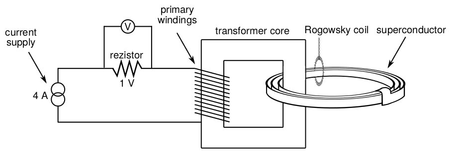
Scheme of the experiment.
The number of turns in the primary winding was 300 in the first experiment and 600 in the second. Current in the primary winding was measured by the voltage on a 1 \(\Omega\) resistor.
Measured data
Superconductive state
All experiments were measured in superconductor state because current changes were so small that they almost disappeared in the noise. Data measured with 300 turns as the primary winding without additional self-inductance of the superconductor is shown in . The decay of the current in the superconductor for different numbers of turns of the primary winding and with or without the ferromagnetic core in the middle of the superconductor coil is shown in figure . The detail of the current rump-up and its time derivation is shown in figure
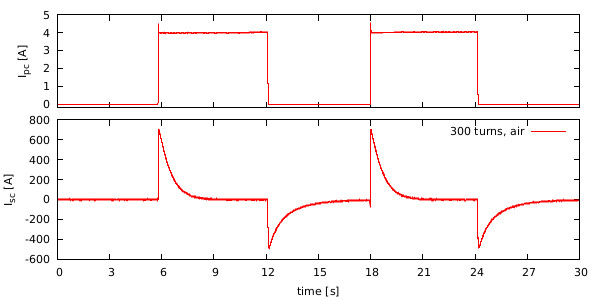
Current in the superconductor depends on the change of the current in the primary winding
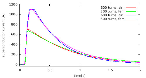
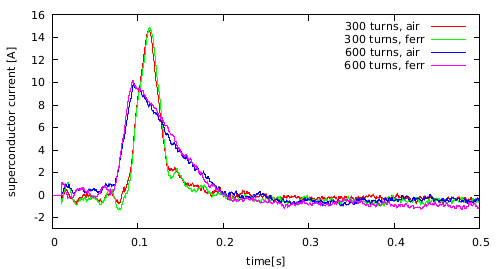
Current in the superconductor for different numbers of turns of the primary winding and different types of the core in the middle of the superconductor coil
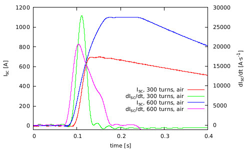
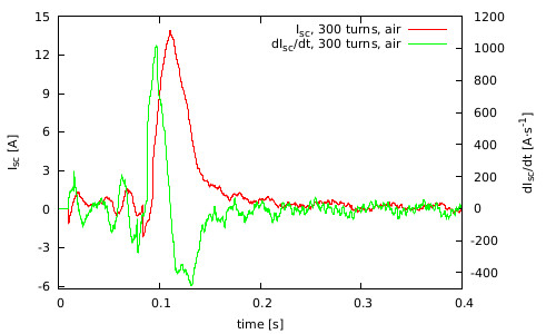
Detail of the superconductor current rump-up (\(I_{sc}\)) and its time derivation (\(dI_{sc}/dt\)) for the different number of turns of the primary winding
The measured data was fitted with the exponential function [exp] to determine the characteristic decay time \(\tau_I\). Resulting data depending on various parametres is shown in
| 300 air | 300 ferr | 600 air | 600 ferr | |
|---|---|---|---|---|
| turning on | \((0,636\pm0,001)\) | \((0,712\pm0,002)\) | \((0,460\pm0,001)\) | \((0,522\pm0,001)\) |
| turning off | \((1,042\pm0,002)\) | \((1,159\pm0,003)\) | \((0,983\pm0,001)\) | \((1,083\pm0,002)\) |
The characteristic decay time \(\tau_I\) depending on the number of the turns of the primary winding and on the type of the core in the middle of the superconductor. The values depend on whether the current supply was turned on or off. The coil was in superconductive state.
Non-superconductive state
The measurement with the coil in non-superconductive state has very low signal-to-noise ratio. To extract signal from the noise the low-pass filter and averaging filter was used. Resulting data is shown in .
| 300 air | 300 ferr | 600 air | 600 ferr | |
|---|---|---|---|---|
| turning on | \((0.016\pm0.004)\) | \((0.0105\pm0.0008)\) | \((0.0235\pm0.0004)\) | \((0.0210\pm0.0009)\) |
| turning off | \((0.084\pm0.003)\) | \((0.093\pm0.001)\) | \((0.102\pm0.001)\) | \((0.0970\pm0.0003)\) |
The characteristic decay time \(\tau_I\) depending on the number of the turns of the primary winding and on the type of the core in the middle of the coil. The values depend on whether the current supply was turned on or off. The coil was in non-superconductive state. [tab_2]
Current in the coil in non-superconductive state for different numbers of turns of the primary winding and different types of the core in the middle of the coil
Detail of the coil current rump-up (\(I_{sc}\)) and its time derivation (\(dI_{sc}/dt\))
Discusion
The characteristic time decay was determine as \(\sim\!0.5\) s for the coil in superconductive state and \(\sim\!0.02\) s for the coil in non-superconductive state. The time decay for the turning off cannot be used due to the long shutdown time of the current supply. The resistance of the coil in superconductive state dropped about 25 times towards the non-superconductive state.
In the first approximation consider a superconductor as a wire with the circular cross-section. This wire has the same cross-section area as a superconductor (\(1.5\) mm\(^2\)). The self-inductance of the secondary winding can be than estimated at 37 \(\mu\)H. This value can be used to determine the resistance of the coil at \(1.6\cdot10^{-4}\ \Omega\,\textrm{m}^{-1}\) for the coil in superconductive state and \(3.9\cdot10^{-3}\ \Omega\,\textrm{m}^{-1}\) for the coil in non-superconductive state.
Conclusion
The superconductor was used as a secondary winding of a transformer. The primary winding was connected to the current supply. The voltage in the superconductor was induced by turning on and off the current power supply. Follow current decreased proportionally to \(e^{-\frac{R}{L}t}\). The decay constant was fitted from the data and the characteristic decay time \(\tau_I\) was determined as \(\sim\!0.5\) s, depending on the number of turns of the primary winding and the type of the core in the middle of the superconductor coil.
Photographs
All photos are in photogallery.