SW/LabVIEW/DAQ/Continuous_analog_input
#Continuous analog input in LabVIEW
Block diagram is shown on 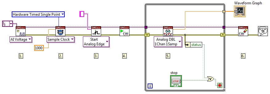 .
.
###Creating Channel creates an analog input voltage.

- physical chanels - input channel (or channels) (use the roll-out menu).
- minimum / maximum value - value uses for set the range and sensitivity of the measurement
- input terminal configuration - set the ground - default (LabVIEW chooses itself), RSE, NRSE, Differential, Pseudodifferential
###Timing setting the timing parametres of the task
- task/channels in - input task (obtained from the Creating Channel)
- rate - setting the frequency of the acquisition (in Hertz)
- Sample mode
- Finite or Continuous Samples - uses buffer (warning: cards PCI/PCIe - 6251 have buffer at least 2, you can not acquire 1 sample, use arrays).
- Hardware Timed Single Point - uses no buffer. Samples are acquired or generated continuously. You have ti ensure, that you have samples ready to write or read. Uses for to know, if the readign or writing executes at a given amount of time.
- Samples per channel - determines number of samples per channel in Finite sample mode, in Continuous Samples determines the buffer size
- Source - input channel for the external clock( if you do not want to use the internal on-board clock)
- Active edge - read/write on at the rising or falling edge
###Triggering the task will wait for the trigger. If the trigger is analog, the input channel is in the String format (e.g. /Dev6/APFI0). If the trigger is digital, you can choose the input channel from the roll-out menu.
