Impact of toroidal magnetic and electric fields on the floating potential of the glow discharge on the GOLEM tokamak
Introduction
Goal of this session conducted in 8th November 2012 at GOLEM tokamak was to study spatial floating potential dependence \(U_f(z)\) of glow discharge induced in tokamak chamber for various toroidal electric fields (current-drive) in H and He plasma for various initial pressure values.
Floating potential sensor deployed on GOLEM consists of linear array of 16 cylindrical tips, each of radius \(R=0.35 \mathrm{mm}\) and length \(b = 2 \mathrm{mm}\). Array spacing is \(a=2.5 \mathrm{mm}\). Every tip is grounded by 1/101 divider consisting of resistors 6 \(\mathrm{k\Omega}\) and 600 \(\mathrm{k\Omega}\).
Tips were oriented radially outward from torus center. Outermost 12 tips were connected through divider to 12 channel 16 bit Data Acquisition Systems (DAS) referred as “Papouch_Zacek” or “Papouch_Za” in GOLEM documentation. Channel zero is the tip of the probe neareast its end. Parameters of Papouch_Zacek are 1 MHz sampling frequency and range \(\pm 10 \mathrm V\). One shot consists of about 35 ms of data with 1 \(\mu\)s resolution.
We induced glow discharge in GOLEM tokamak chamber by electrode with potential +1000 V with respect to chamber vessel.

GOLEM rake probe

Rake probe immersed in He glow discharge (shot 10262)
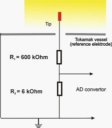
Rsistor divider of one tip
Automatized session summary is available here.
We have made decision to find non-invasive magnetic field during testing shots and use this value for rest of the session. Then we measured floating potential temporal and spatial dependence with different current-drive capacitor voltage at fixed pressure in He plasma. Second part is intended to scan through pressure dependence of H plasma with fixed current-drive field. The last part tried to detect plasma in highly evacuated chamber with and without pre-ionization (thermoemissive wire) and with previously used rather weak current drive.
Test shots sequence
Test shots sequence was aimed to verify electrical connection and to found non-invasive magnitude of magnetic field. We required initial pressure 725 mPa and we tried different values of initial voltage on capacitor bank \(U_\mathrm{B}\) for toroidal magnetic field \(B_t\). No current drive is applied in Test shots sequence.
Channels number 7, 9 and 11 were found defective. (The first channel furthest from chamber wall is channel number 0, the last channel is number 11.)
We have found non-invasive toroidal magnetic field roughly up to 200 \(\mu\mathrm T\) by 2 V on capacitor bank. This toroidal field was used for the rest of the session.
 Shot 10250: \(U_\mathrm{B}\) = 20 V, peak toroidal field \(B_t\) ca 9 mT. Glow discharge destroyed by ca 6 mT toroidal magnetic field. |
 Shot 10251: \(U_\mathrm{B}\) = 10 V, \(B_t\) peak ca 5 mT. Glow discharge plasma altered by magnetic field. Turbulence observed. |
 Shot 10252: \(U_\mathrm{B}\) = 5 V, \(B_t\) peak ca 3 mT. 0.5 mT toroidal magnetic field is enough to noticeable alter plasma. Turbulence observed. |
 Shot 10253: \(U_\mathrm{B}\) = 2 V, \(B_t\) peak ca 140 \(\mu\mathrm T\). We didn’t detect influence of toroidal magnetic field under 140 \(\mu\mathrm T\) (ambient Earth magnetic field is ca 50 \(\mu\mathrm T\)). Steady state observed. |
Calibration
Following part is under discussion!
We can conclude that perturbation due to magnetic field is negligible for the last shot 10253 in testing sequence. Because electric fields should be screened at few \(\lambda_D \approx \mathrm{few} 10 \mu m\) distance and temperature profile should be flat there is no reason for measured electric field.

Shot 10253: Negligible toroidal fields. Due to sub-millimeter scale of Debye length there should not be electric field.
We have made calibration by such coefficient per channel that average of given channel of #10253 equals average floating potential of shot #10253. Calibration vector is found
\[(0.948, 0.967, 1.175, 1.077, 1.109, 0.959, 0.993, NaN, 1.029, NaN, 0.831, NaN).\]
Channels number 7, 9 and 11 (first is 0) are defective and values are masked to NaN. Used calibration routine is available here .
Current driven He glow discharge
We kept toroidal magnetic field peaking at 140 \(\mu\mathrm T\) (2 V on capacitor bank) and we varied toroidal electric field generating capacitor bank voltage \(U_{\mathrm{CD}}\). We required initial pressure 725 mPa.
 Shot 10254: Current drive capacitor bank \(U_{\mathrm{CD}}=5\mathrm V\), current drive loop voltage \(U_L\) ca 0.6 V peak. |
 Shot 10255 Current drive capacitor bank \(U_{\mathrm{CD}}=10\mathrm V\), current drive loop voltage \(U_L\) 0.6 V peak. |
|
Data acquisition failure. Shot 10256 Current drive capacitor bank \(U_{\mathrm{CD}}=20\mathrm V\), current drive loop voltage \(U_L\) 1.2 V peak. |
 Shot 10257 Current drive capacitor bank \(U_{\mathrm{CD}}=20\mathrm V\), current drive loop voltage \(U_L\) 1.2 V peak. |
 Shot 10258 Current drive capacitor bank \(U_{\mathrm{CD}}=40\mathrm V\), current drive loop voltage \(U_L\) 1.8 V peak. |
 Shot 10259 Current drive capacitor bank \(U_{\mathrm{CD}}=80\mathrm V\), current drive loop voltage \(U_L\) 3 V peak, turbulent. |
 Shot 10260 Current drive capacitor bank \(U_{\mathrm{CD}}=160\mathrm V\), current drive loop voltage \(U_L\) 5 V peak, turbulent. |
 Shot 10261 Current drive capacitor bank \(U_{\mathrm{CD}}=320\mathrm V\), current drive loop voltage \(U_L\) 9 V peak, turbulent. |
 Shot 10262 Current drive capacitor bank \(U_{\mathrm{CD}}=320\mathrm V\), current drive loop voltage \(U_L\) 9 V peak, turbulent. Repeated for video record. |
Conclusion
Rake probe calibration
The steady state of glow discharge was measured and the expected Debye length forbids measured electric field. This can be caused by sensor harness or resistor divider. Calibration was based on this fact and calibration vector was found.
He glow discharge in toroidal electric field
Toroidal electric field was found to be causing turbulences from ca 3 V per loop. Floating potential generally tends to drop after few milliseconds of electric field which can be caused by plasma cooling, because floating potential is dependent mainly on plasma temperature. But we can’t forget to currents going to divider resistors (few tens of \(\mu A\)) introducing current and thus plasma density dependence.
TODO Model
There is also interesting time evolution of floating potential under current drive. Moderate loop voltage (few hundreds mV) forces floating potential to decrease and stabilize on lower level. High loop voltage (from 1 V up) can cause further decrease after short interval (few ms) of stable potential and eventually second stabilization.
TODO Multiple Maxwellian distribution? Some neutralization/ionization process?
TODO Turbulence of current-driven plasma can be two-beam instability?
Further objectives
- To explain measured floating voltage differences.
- To explain time evolution of current-driven glow discharge (stable/decreasing potentials)
- To develop model of Langmuir probe in current-driven plasma.
- Explain what is process behind floating potential high frequency turbulent signal.
- To implement fast swept device to acquire IV curve. Time resolution should be better than one full IV curve per 1 ms and channel.