Toroidal magnetic field measurements
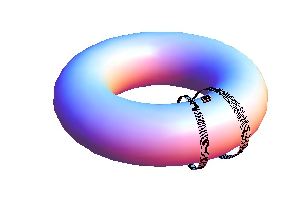
The toroidal magnetic field \(B_T\) is measured by a small coil (called the \(B_T\) coil) fixed to the tokamak upper outboard side, its axis pointing along the torodial direction. The general principle of magnetic coil measurements is described here. The \(B_T\) coil is one of the basic GOLEM diagnostics.
|
|
|
Coil description
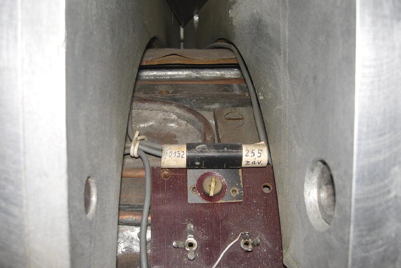
The \(B_T\) coil is made of 255 turns, each having a diameter of \(10 \, \mathrm{mm}\). Its effective area is therefore \(0.02 \, \mathrm{m}^2\). Its exact coordinates in the \((R,Z)\) plane are not known but this isn’t an issue; see below. The coil voltage is collected by the DAS1 data acquisition system.
Coil effective area for area-averaged \(B_T\) measurements
There is a large loop encircling the tokamak chamber in the poloidal direction; its radius is \(0.145 \, \mathrm{m}\) and its area is \(0.066 \, \mathrm{m}^2\). Even though it is not currently part of the tokamak diagnostic system, it can be used for measurements of \(B_T\) averaged over the entire loop area. It was measured that when the \(B_T\) coil signal is averaged over this area (considering that \(B_T \sim 1/R\)), its sensitivity is \(5.98 \div 6.06\) times lower than the large loop sensitivity. This implies that the \(B_T\) coil effective area is \(0.066 \, \mathrm{m}^2 / 6 = 0.011 \, \mathrm{m}^2\) when it’s used for area-averaged \(B_T\) measurements.
\(B_T\) measurement
Cannonically the toroidal field \(B_T\) is always given at the chamber centre. This is because it falls with the major radius as \(B_T \sim 1/R\), and so a fixed measurement location is required to compare between various tokamaks and discharges. Unfortunately the \(B_T\) coil is not located at \(R=R_0\); rather it is further outside. However, since the chamber doesn’t move anywhere and neither does the coil, the ratio \(B_{T0}/B_{T,coil}\) is fixed. Many years ago a calibration experiment was conducted where a measuring coil was inserted into the centre of the tokamak chamber. By comparing its signal to the \(B_T\) coil signal, the following calibration relation was derived:
\[ B_{T0}(t) = 70.42 \, \mathrm{T/Vs} \int_0^t V_{coil}(t') \mathrm{d}t' \]
Here \(V_{coil}\) is the voltage induced on the \(B_T\) coil. The constant \(70.42 \, \mathrm{T/Vs}\) [source] is several calibration constants combined into one. It includes both the calibration “induced voltage \(V_{coil} \rightarrow\) magnetic field \(B_{T,coil}\)” (featuring the number of coil turns and the coil effective area) and the calibration “\(B_{T,coil} \rightarrow B_{T0}\)”.
Various links
A basic block diagram of signal processing: bd_dB_t.pdf
Photos of the \(B_T\) coil: /Diagnostics/Basic/ToroidalMagneticField/PhotoGallery/
Alternative, outdated page on \(B_T\) measurement: diagnostics_torcoil
To do
find which DAS the \(B_T\) coil is plugged into
procure a general magnetic coil signal processing guide