Diagnostics/Magnetic/MirnovCoilsAtLimiter/Theory/diagnostics_mirnov
Mirnov Coils
Principle of Operation
Currently, the most used form of magnetic field measurement in the fusion research, is by use of magnetic coils. This diagnostics method is based on integral form of Faraday’s law:
It can be seen that integral on the left-hand side is reduced into voltage U detected at the ends of the wire of coil and the right-hand side integral is turned into product of effective area of coil S and time-derivation of averaged magnetic field magnitude in the coil B. Once again, it is evident that in order to obtain measured quantity (magnetic field), it is necessary to integrate the measured voltage U.
Characterization and Parameters of Sensor
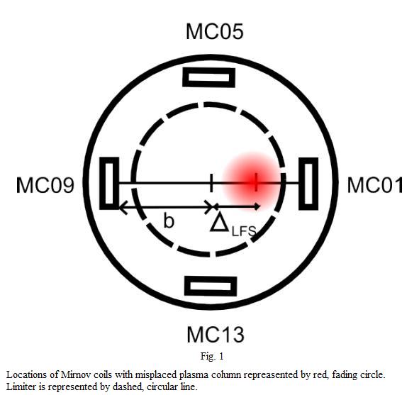
There are currently 4 Mirnov coils placed on tokamak GOLEM altogether. All the 4 coils are located on a single circular rack located inside of the liner. Diameter of the rack is 93 mm and locations of respective coils are depicted in fig. 1. It is evident, that configuration of Mirnov coils determines them for purposes of poloidal magnetic field BP measurement, ergo field generated by plasma current. As can be seen in fig. 1, difference of BP magnitude on opposite coils can be used for evaluation of plasma column displacement. (More about the determination of the plasma position is in this page.)

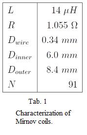
Since the coils are placed inside of liner (even though behind limiter radius), each of them is enveloped by a ceramic cylinder made of porolite for their protection and insulation from plasma particles. All the coils are of same design and their properties are summarized in tab. 1.

Here, L denotes inductance of the coil and R stands for its resistance. Dwire represents diameter of wire of coil. This wire is wound in two layers with diameter Dinner or Douter respectively, having 91 turns in total. Effective area of the coil is thus:
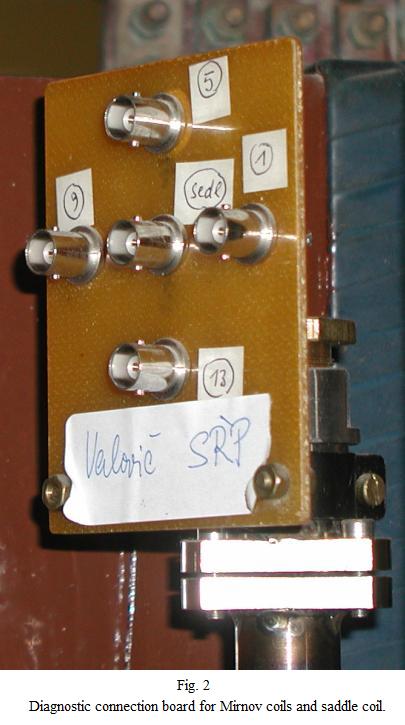
Since all the Mirnov coils are fixed on a rack placed deep inside of liner, their photodocumentation is not available. However, in fig. 2, there is depicted a diagnostic board containing signal ports of all the Mirnov coils and of a saddle coil.
Subtraction of Toroidal Field Cross-Talk and Final Relation
Even though the purpose of Mirnov coils is to measure BP induced by plasma current, due to imperfect alignment of the coils MC01, MC05 and MC09, cross-talk signal of BT is picked along with the BP signal. Thus, for correct evaluation of measured BP, it is necessary to eliminate the cross-talk signal. There are two methods of how to carry this out. First one is trivial - by making a vacuum shot (i.e. the shot without plasma), it is possible to obtain absolute values of this parasitic signal for each coil for given discharge parameters configuration. This values can be resultantly subtracted from raw signal of Mirnov coils in plasma shot (for given discharge parameters). However, making an extra shot in every experiment would be more time and resource demanding. Thus the second method is preferred. It is based on weighting of BT signal obtained by toroidal magnetic field measurement coil to signal of BT cross-talk on respective Mirnov coils. The relation for reference coil (represented by toroidal field measurement coil) is as follows:
thus following relation is obtained:
Similar relation can be derived for each of the Mirnov coils as well:
In previous equations, STOR stands for effective area of toroidal magnetic field measurement coil and Scoil represents area of misalignment of Mirnov coil. Since the purpose of this method is to eliminate BT cross-talk by use of toroidal field measurement coil, it is assumed that left-hand sides of both of two previous equations are equal to each other (even though it is not true that BT magnitude is the same in their respective places – this principle is based on weighting of signals, not actual values of quantities). With this, following relation is obtained:

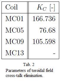
for each time moment t. In this manner, weighted, dimension-less constants KC of Mirnov coils misalignment are obtained. Their values can be found in tab. 2.

Please note that missing value in the case of MC13 represents that misalignment of this coil was not detected. Finally, after obtaining the KC constants, the final relation of poloidal magnetic field signal evaluation can be written in following manner:
