Plasma current measurements using the Rogowski coil
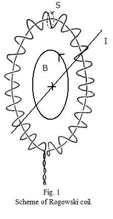
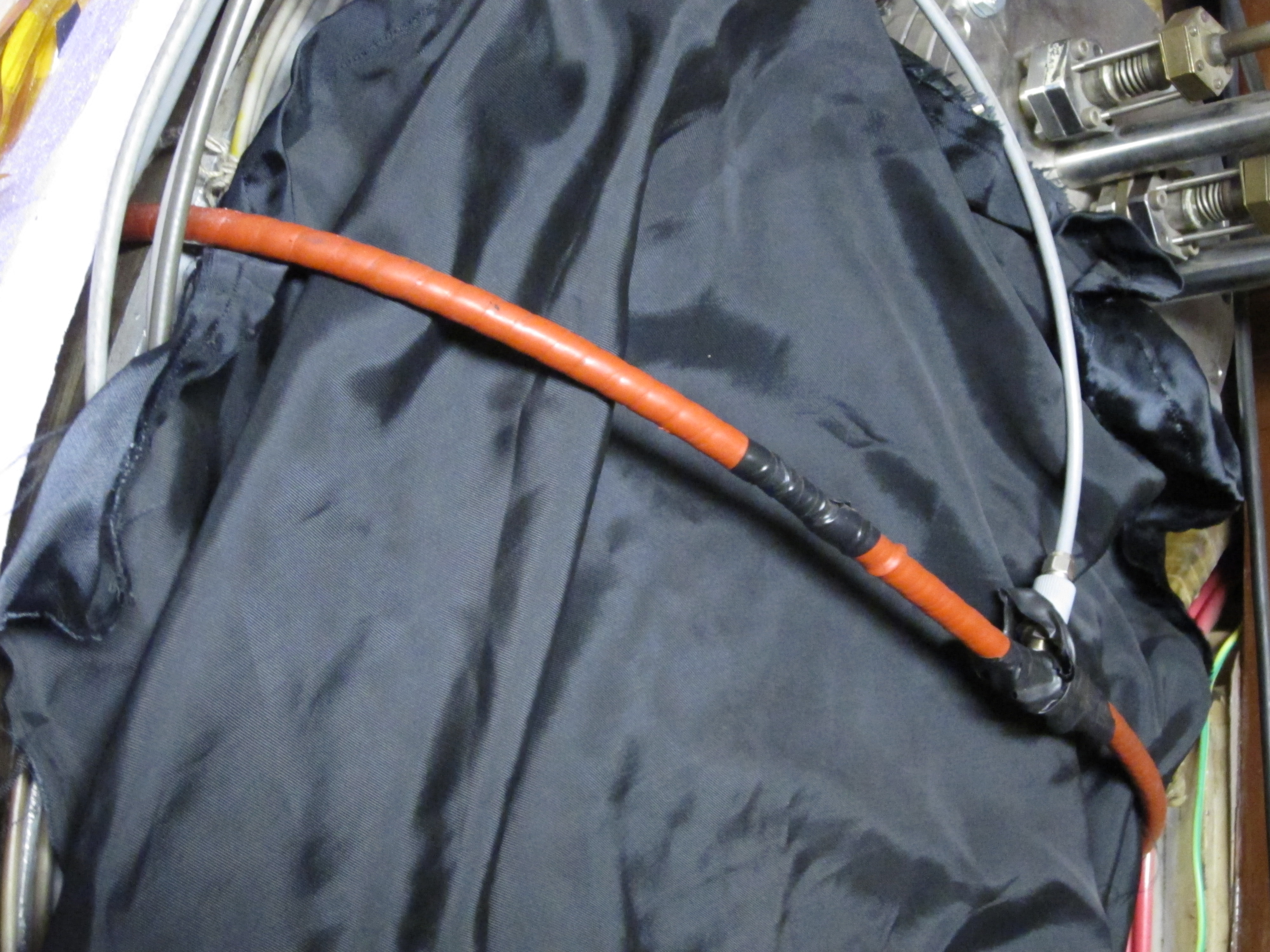
The plasma current \(I_p\) is measured with a Rogowski coil (see picture below). The Rogowski coil is wound around the tokamak chamber in the poloidal direction.
|
 Rogowski coil |
Note that the Rogowski coil is back-wound - one of its ends is folded and threaded back along the loop. This is necessary to negate the toroidal field contribution to the coil signal. As a result, both of the Rogowski coil contacts are at one end of the loop.
#Theory of Rogowski coil measurement
The Rogowski coil measures the plasma current via Amper’s law (magnetic field around a conductor is directly proportional to the current running through it) and Faraday’s law (changes of magnetic field cause voltage induction on surrounding loops/coils). In the case of tokamak plasma, Amper’s law is
\[\oint_l B_p \mathrm{d}l = \mu_0 I_p\]
where the integration path \(l\) poloidally encircles the tokamak chamber as in Fig. 1, \(B_p\) is the poloidal magnetic field, \(\mu_0\) is the vacuum permeability and \(I_p\) is the plasma current. The total magnetic flux \(\Phi\) in the Rogowski coil is then:
\[\Phi = n \int_S \mathrm{d}S \oint_l B_p \mathrm{d}l = nS\mu_0 I\]
where \(n\) is the number of coil turns per unit of length and \(S\) is the area of a single coil loop (given that all the turns are of the same area). During a GOLEM discharge, the plasma current ramps up from zero to some maximum value and then begins falling again, which changes the magnetic flux in time and cause a voltage \(U\) to be induced between the Rogowski coil ends:
\[U = -\frac{\mathrm{d}\Phi}{\mathrm{d}t} = -\mu_0 n S \frac{\mathrm{d}I_p}{\mathrm{d}t}\]
To calculate the plasma current \(I_p\) from the Rogowski coil voltage \(U\), the signal must be integrated and calibrated (see the next two sections).
#Rogowski coil signal processing
General aspects of magnetic coil signal processing, such as numeric integration and offset removal, are described here. In the case of Rogowski coils another specific complication appears - the coil doesn’t pick up only the plasma current, but also the current running through the tokamak chamber. Since the chamber is toroidally conductive, it responds to the transformer action by developping a toroidal current of its own. The total current \(I_{total}\) encircled by the Rogowski coil is then
\[ I_{total} = I_p + I_{chamber}\]
and the chamber current \(I_{chamber}\) must be subtracted from the current obtained by integration. Luckily the chamber current can be easily calculated via Ohm’s law,
\[ I_{chamber}(t) = \frac{U_{loop}(t)}{R_{chamber}}\]
where \(U_{loop}\) is the loop voltage and \(R_{chamber}= 9.7 \times 10^{-3} \Omega\) [source] is the chamber resistivity.
Rogowski coil parameters
The coil parameters are summarized in the following table:
coil length | \(l = 230 \, \mathrm{cm}\) |
wire diameter | \(D_{wire}=0.3 \, \mathrm{mm}\) |
coil diameter | \(D_{coil} = 7.9 \, \mathrm{mm}\) |
number of turns per metre | \(n = 3000 \, \mathrm{m}^{-1}\) |
Finally, the calibration factor \(K\) in the equation
\[ I_{total}(t) = K \int_0^{t} U(t') \mathrm{d}t' \]
is \(K = 5.3 \times 10^6 \, \mathrm{AV}^{-1}\mathrm{s}^{-1}\) when the signal is sampled with \(\Delta t = 10 \, \mu s\). Please note that this value was determined by empirical means and thus it differs slightly from the theoretical value which can be calculated from the coil parameters.